
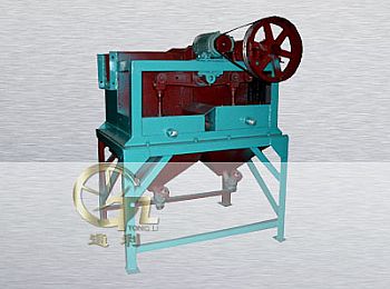
Diaphragm Jig
1,Overview
Diaphragm jig has simple operation, large capacity, and can obtain the final concentration or the tailing in one beneficiation. So it is widely used in dealing with the coarse or medium-grained ore. It is suitable for classification the larger differential density of tungsten, tin, iron, manganese and chrome ore; also for ferrous metal and non-ferrous metals containing the gold and rare metals.
2,Structure
LTP300×450 Rectangle Compartment Side Way Action Type Jig is mainly composed of jig box drive device, water distribution, diaphragm and bibcock. There are two jig buckets with different sizes and each diaphragm is divided into jig area and diaphragm area by clapboard. The rubber diaphragm pumping to make medium (water) moving is the jigging course. The triangle belt drives big belt pulley by electromotor so connecting rod of the eccentric gear and rocker are up and down moving. Another connecting rod is connected with the rubber diaphragm which is moving up and down to jig.
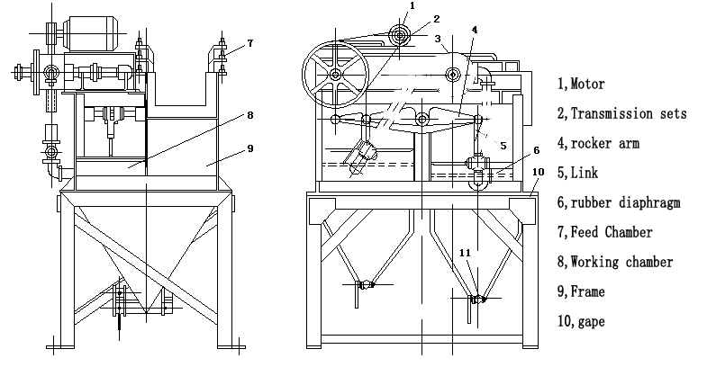
Based on the size of ore, we can change the stroke of connecting rod and choose different stroke to make the best jigging effect. The method of altering stroke per minute is to exchange a smaller belt pulley but there are two strokes per minute: 322r/m; 420r/m. The method of choosing stroke is to loose bolt and screw cap, take out bowel and move the relative place between eccentric adjusting sieve and eccentric shaft so there are 11 different strokes (0-25.3mm).
Because of a sieve added on the working screen, the jig can be processed the uneven sizes of material. (Note: the sieve can be requested to supply or not). After the feed ores are sent to jig chamber, the ores are separated to different layers in the medium by the pulsation of diaphragm. The light but weight is sank to the tank of jig bucket through the spaces of materials of artificial bed layer and its sieve holes but the coarse but light is washed to the discharge end of screen by medium. Because the back jig chamber is lower 50mm than front jig chamber, the light ores is overflowed through front jig chamber to the back chamber and jigged again. If needed, the place of end plate can be adjusted to control the discharge amount. The concentrate in tank can be discharged by discharge tube regularly.
3,Technical Specifications
|
model
|
chamber
(No)
|
jig
area
(m2)
|
Feed
Size
(mm)
|
Capacity
(t/h)
|
Stroke
(mm)
|
Frequency
(r/min)
|
Supply
Water
Rate
(t/h)
|
Water
Pressure
(kg/cm)
|
Power
(kw)
|
|
100×150
Diaphragm jig
|
1
|
0.15
|
-3
|
0.18-0.6
|
-
|
420
|
-
|
1-1.5
|
0.55
|
|
300×450
Tow-Room Diaphragm Jig
|
2
|
0.27
|
-12
|
3-6
|
0-26
|
322
|
2-4
|
1-1.5
|
1.1
|
|
1000×1000
Underside
Acting Cone Jig
|
2
|
2
|
1-5
|
10-25
|
0-26
|
200-350
|
60-80
|
0.6-2
|
1.5
|
|
370×360
Underside
Acting Cone
Diaphragm jig
|
2
|
0.26
|
6
|
1-3
|
5-25
|
200-250
|
2-5
|
-
|
1.1
|
|
Trapezoid
Diaphragm jig
|
3
|
2.7
|
-3
|
12.5-37.5
|
13-21
|
170-230
|
60-90
|
2
|
1.1
|
|
670×920 Jig
|
2
|
1.44
|
4-8
|
7-10
|
18-24
|
240-300
|
-
|
-
|
|
|
NOTICE:
1. Please make sure the screws of each part in tight and there is no leaking in stopcock before the starting.
2. Please replenishment lubricating oil in the each nipple frequency.
3. The load revolution only permits after the empty load revolution in normal.
4. The oil stain on the rubber diaphragm and the triangle belt are not allowed.
|
|||||||||
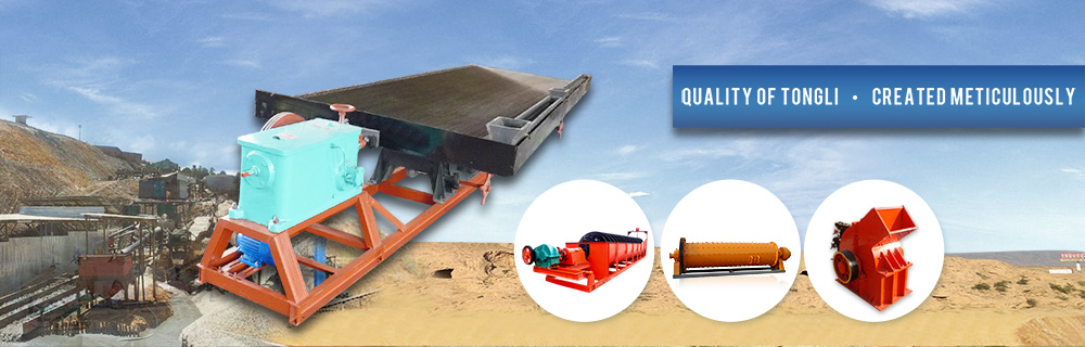
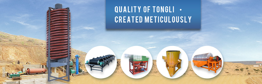
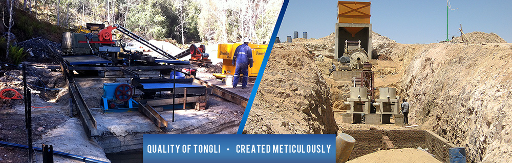
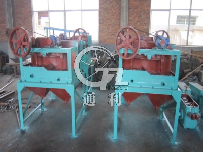
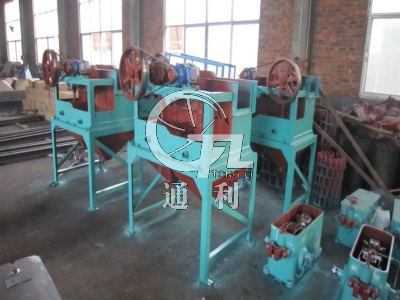
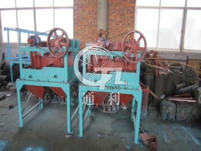
4,Application Scenarios
| Production Scenarios | Production Scenarios | Production Scenarios |
 |
 |
 |